
This page contains affiliate links. As an Amazon Associate we earn from qualifying purchases.
A 14-Step DIY Video Guide
This is a step-by-step guide to installing a diverter valve below a bathtub/shower drain and running the graywater outside to a mulch basin instead of down the sewer line. We documented the entire install on video, broken here into 14 short chapters — many under a minute, some closer to two or three — so you can watch exactly how each step was done before you try it yourself.
Everything here follows the same pattern laid out on our main Build page:
- The three-way diverter valve is the heart of the operation.
- An airlock vent is not necessary in this case because we don’t worry about siphoning out new water coming into the bathtub like we would in the laundry machine.
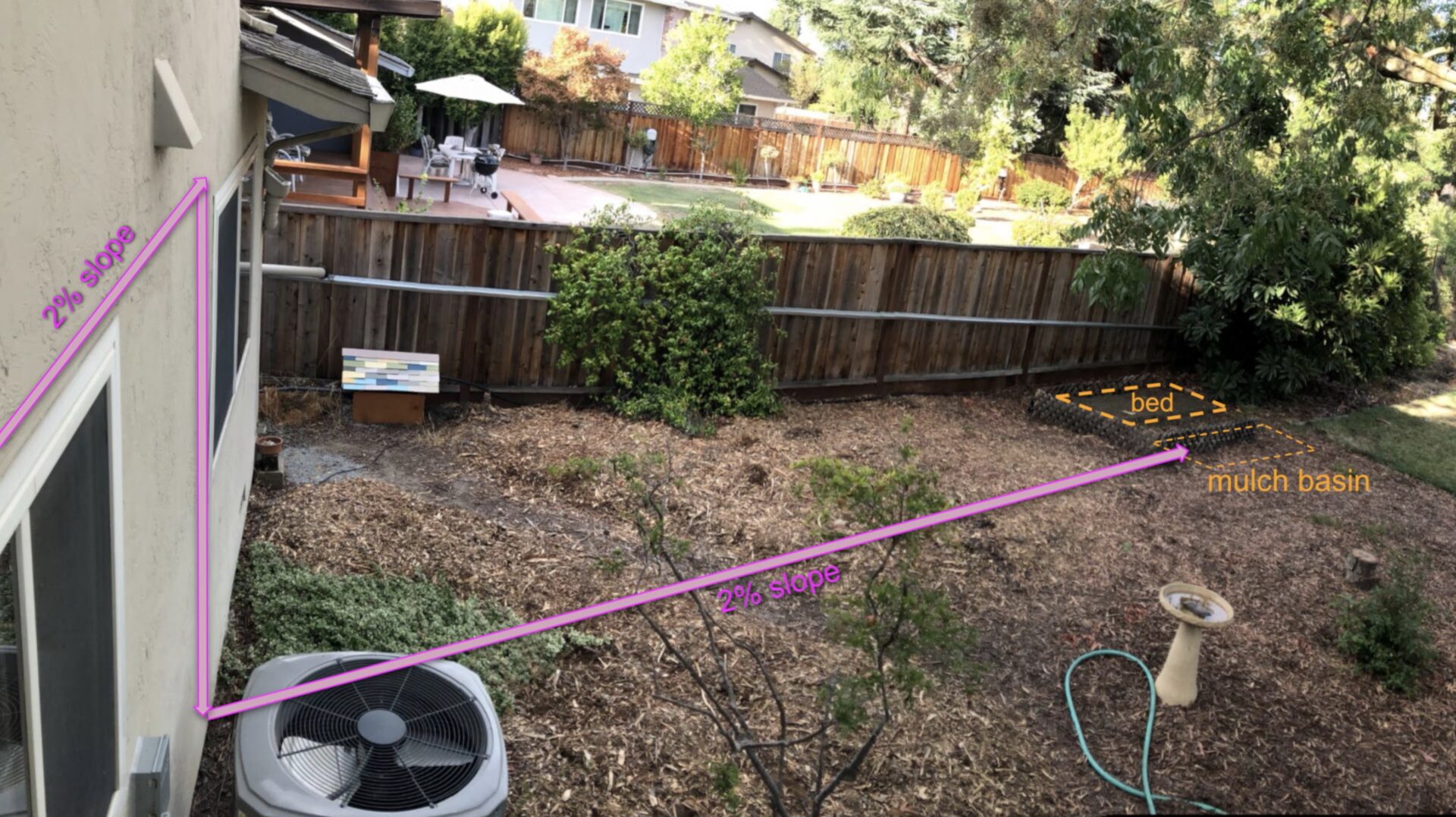
- A slope of 2% (¼ inch drop per foot of run, or at least 1.15º) allows gravity to do the work.
- We distribute water below the surface in a mulch basin, which acts as our biofilter.
- We use the right soaps to protect soil biology.
- We don’t store any graywater.
Planning the Layout
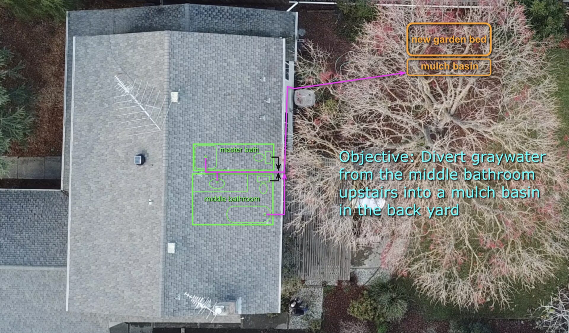
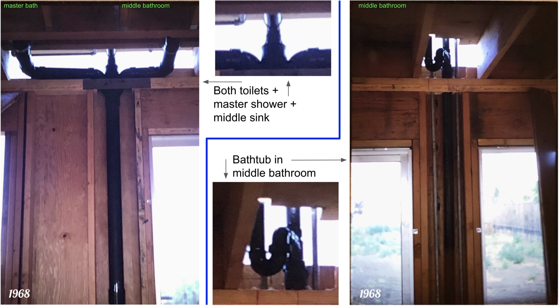
We were lucky to have photos of the house under construction, which showed exactly where the pipes were and where we would need to cut in. It would have been great to get the sink as well, but it was on the other side of the room from the tub and tied in with the plumbing for the toilet, as well as the toilet from the adjacent master bathroom. So it would be tub only.
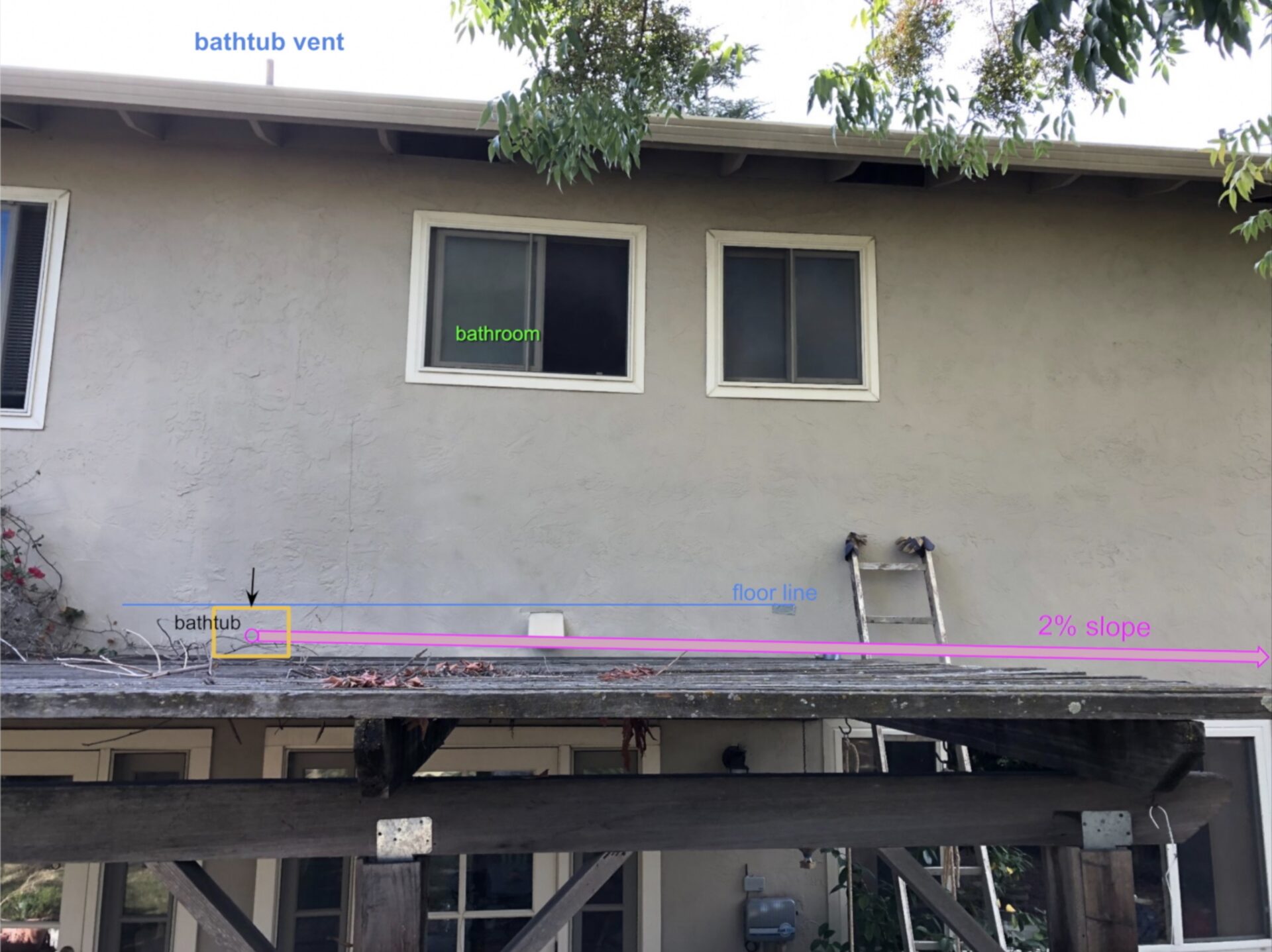
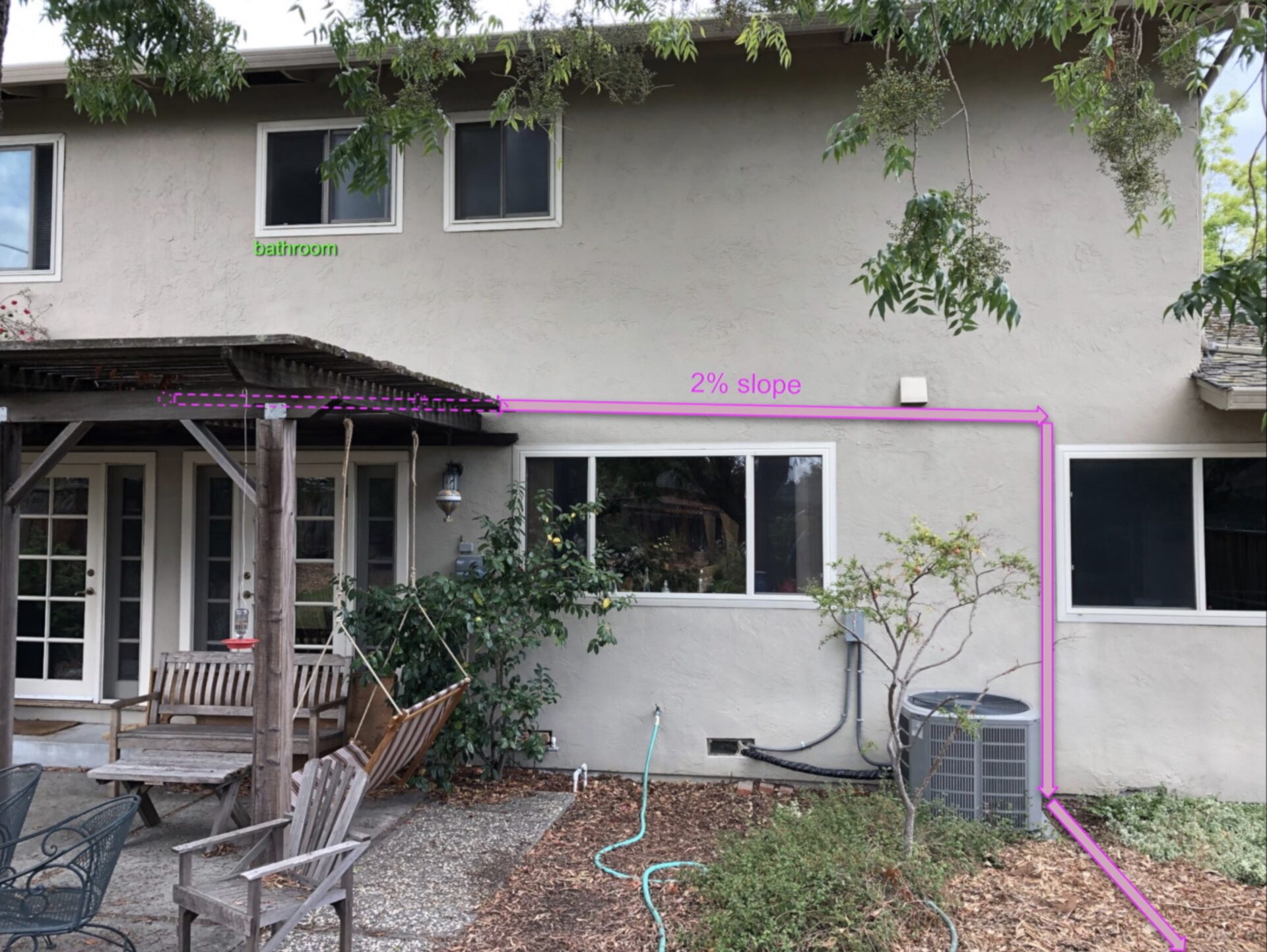
Second floor bathrooms sometimes pose access challenges – see our Retrofit page for an example. In this case, because the drainage plumbing was in the exterior wall, it was easy to cut a small access port and run the new pipes outside.
If the bathroom were farther inside the house, it might be necessary to cut in after the pipes descend below the ground floor, in the crawlspace under the house. That could seriously reduce the amount of fall available for gravity feed, especially once you get outside and need to cover a distance.
Also, since we would alter the existing plumbing of the house, our city requires a permit. See our Legal page and related articles for guidance there.
Step 1: Digging the Mulch Basin and Laying the Outflow Pipes
We started at the end to know whether it was feasible to run a pipe as far as we wanted to – that ¼ inch per foot drop results in accrued depth. Of course, you can easily measure and calculate it, but we wanted a look at the pit in real life.
It was also the cheapest, least invasive part of the whole thing, the aim of all the coming effort, so we felt better making sure that part was in order. “Begin with the end in mind,” as the saying goes.
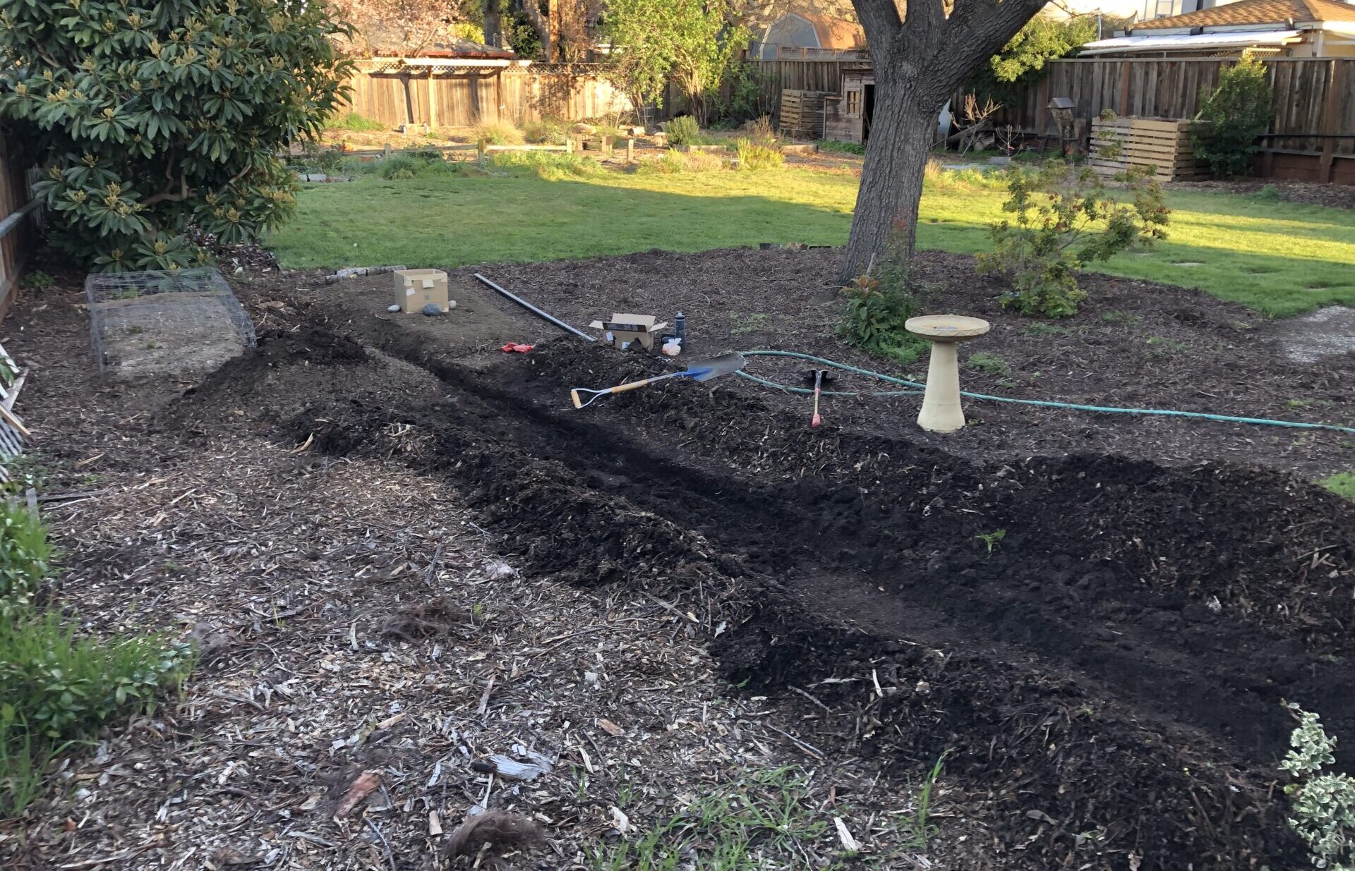
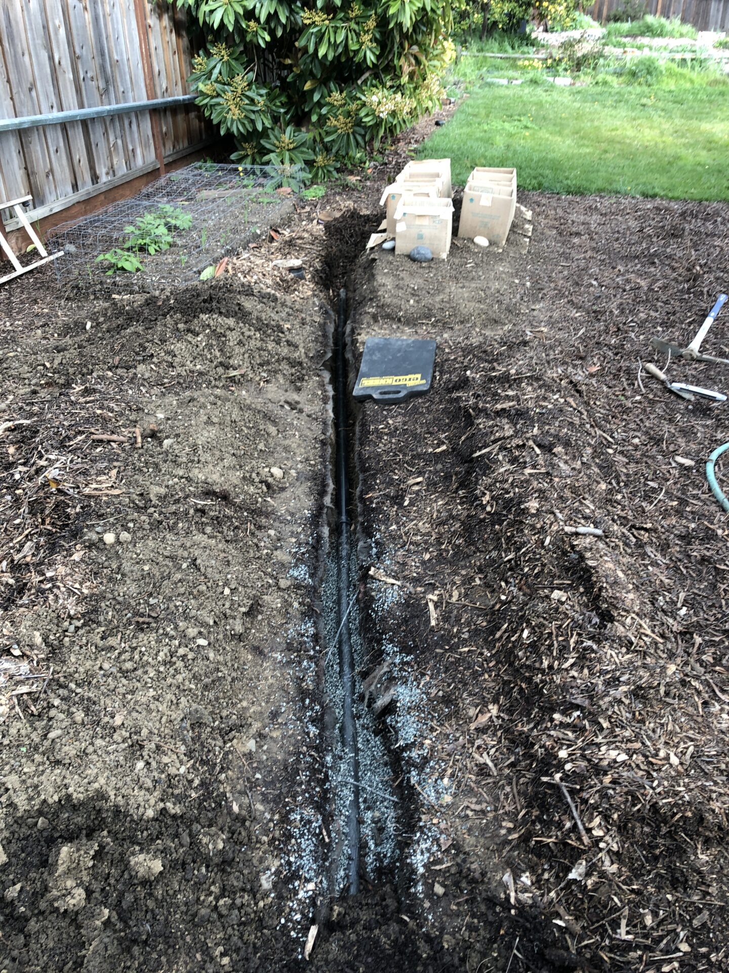
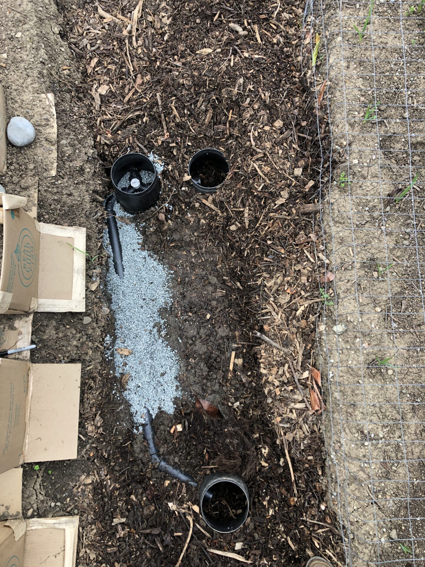
Gravel below the pipes provides a stable base. It may not be necessary to support the entire length with gravel; periodic supports might be enough, with packed dirt filling in the rest. Maintain your slope!
We sized the basin to fit at least the entire contents of a full bathtub, deep enough to allow a drop inside the mulch shields between the pipe and the chips, as well as a few inches more of chips below the bottom of the shields.
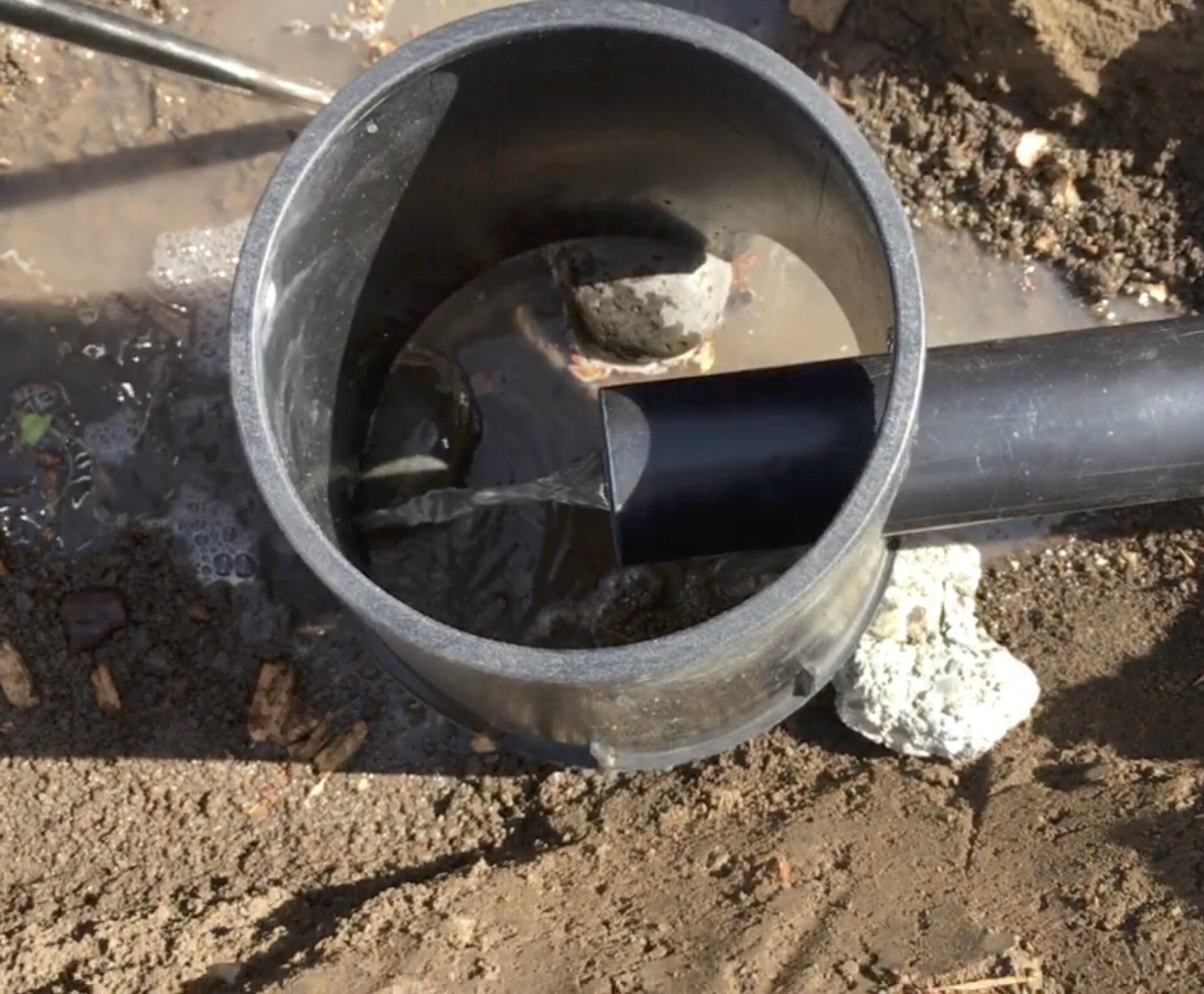
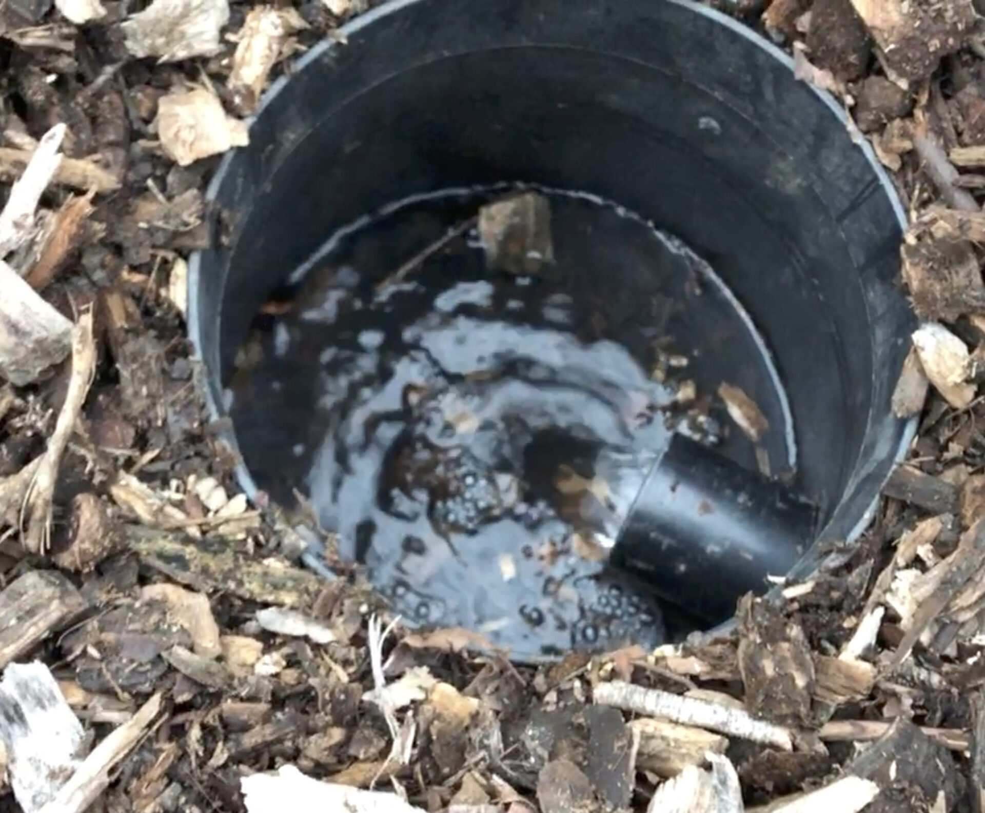
For improved water infiltration, we came back later and drilled a lot of holes in the sides of the mulch shields. Didn’t think of that at picture time.
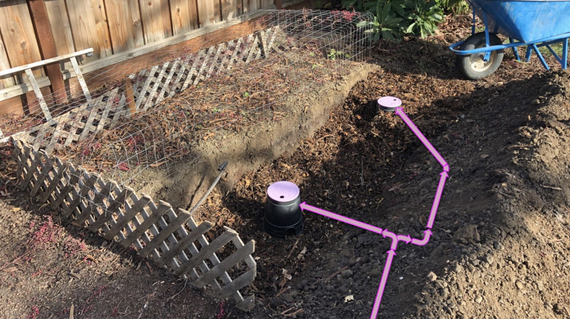
A flow splitter (or double ell, double elbow or double 90) divides the flow evenly as long as you carefully level it, and protect it under a cover of its own. It’s a good idea to re-check the level as part of annual maintenance.
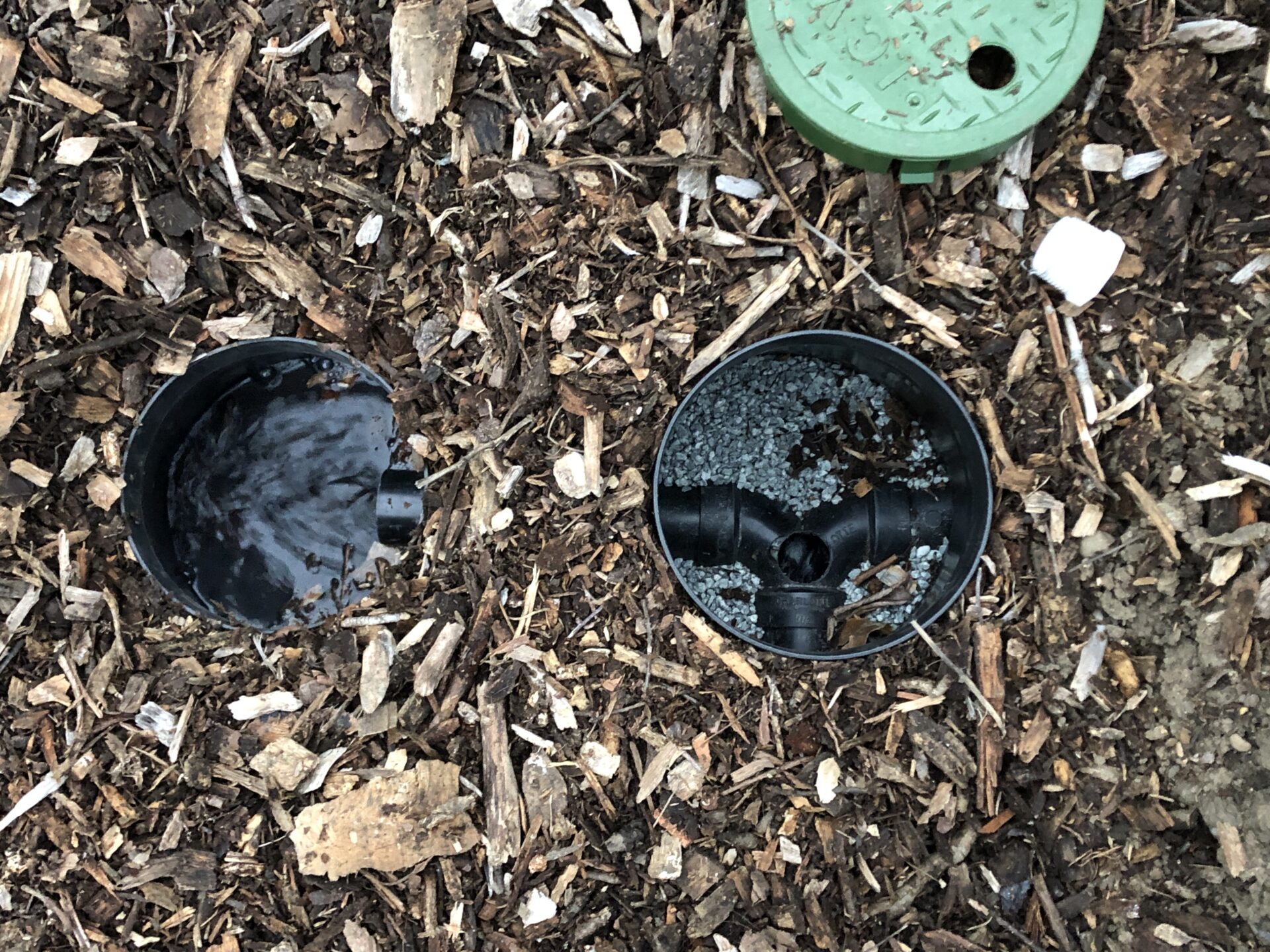
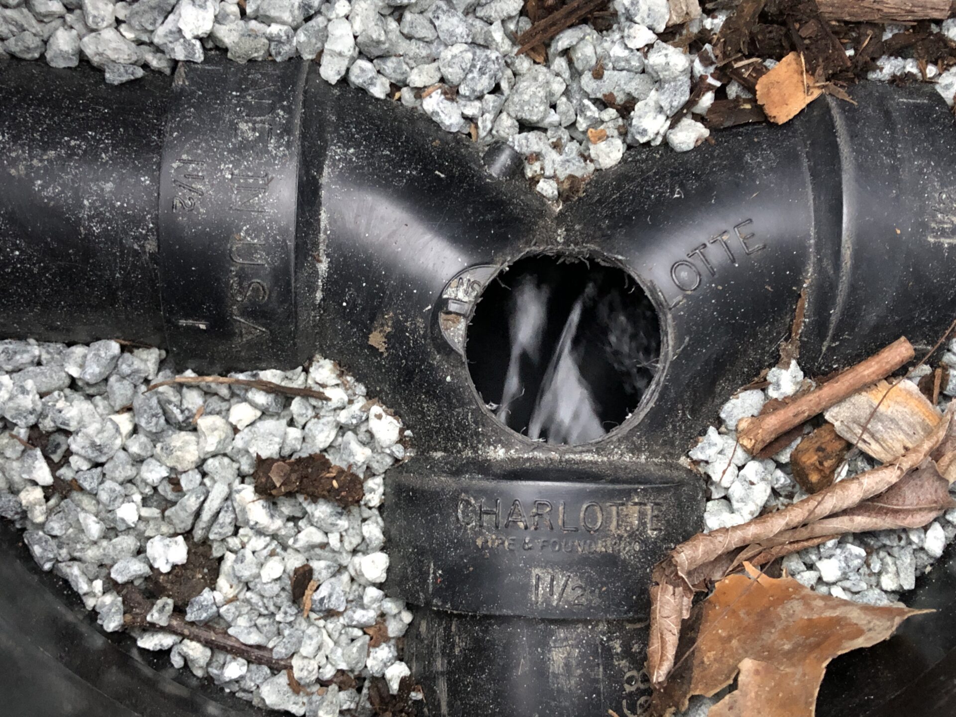
You can find flow splitters pretty easily but you’ll want to cut an access hole in the top with a 1″ hole saw and thread the hole by twisting in a 1″ steel nipple. That way you can plug it with a 1″ threaded cap to keep dirt out. This is how you can inspect the evenness of the flow split as well as clean out any gunk that might get caught over the years.
Once everything is in place, test it out. Get yourself a cheap hand pump and run a garden hose out the window, and adapt it to the outflow pipe:
Step 2: Cutting Open the Wall to Access the Drain
You’re puncturing the envelope of your house at this point, which can be unnerving. If you spend more than a day on this project, carefully seal the opening each time you step away. You don’t want moisture getting inside.
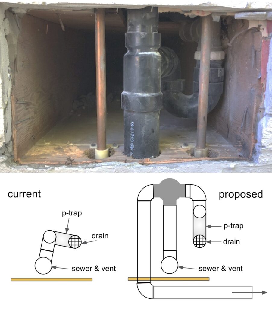
We started with a smaller hole to make sure we were in the right place. Once we could see inside, we expanded it to the edges of the available area.
Then, having assessed the reality of existing pipes, we drew up a plan for where the diversion valve and new pipes would go:
Step 3: Clearing Space for the Diverter Valve
Since the existing drain and vent pipes are still going to be used, and they disappear right away into the house, leave as much as you can. You’ll need to have some pipe for your new fittings to hang onto.
Step 4: Dry-Fitting the Diverter Valve
The three-way valve we use here is different from the 1-inch brass variety used in Laundry to Landscape. These are from the pool and hot tub world, and work for pipes both 1-½ inches and 2 inches. The smaller pipes slide inside the ports, and the larger ones butt up against the ports and use a sleeve type connection. You’ll see both in these videos.
Unlike the brass laundry valves, you can reconfigure this kind to change which port will be the input. Follow the instructions that come with the valve.
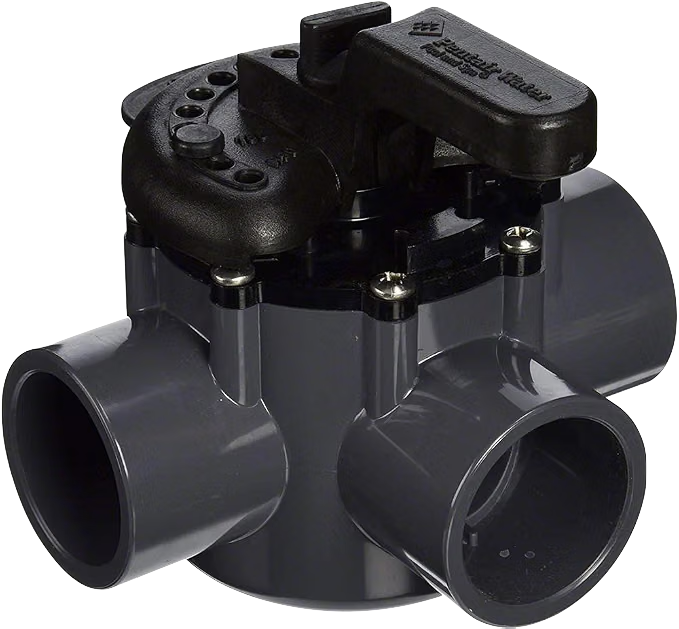
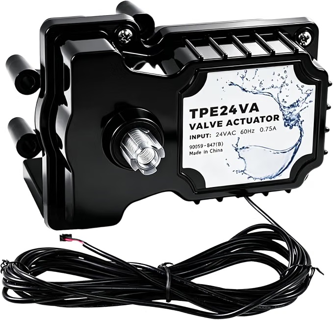
The electric actuator motor is also a pool and spa item. To attach it to the valve, remove the handle from the valve lid after you’ve configured the ports. Seat the actuator where the handle was, over the valve’s center post. There will be screw holes on the actuator that fit onto some of the valve lid’s screw holes.
Here they are attached:
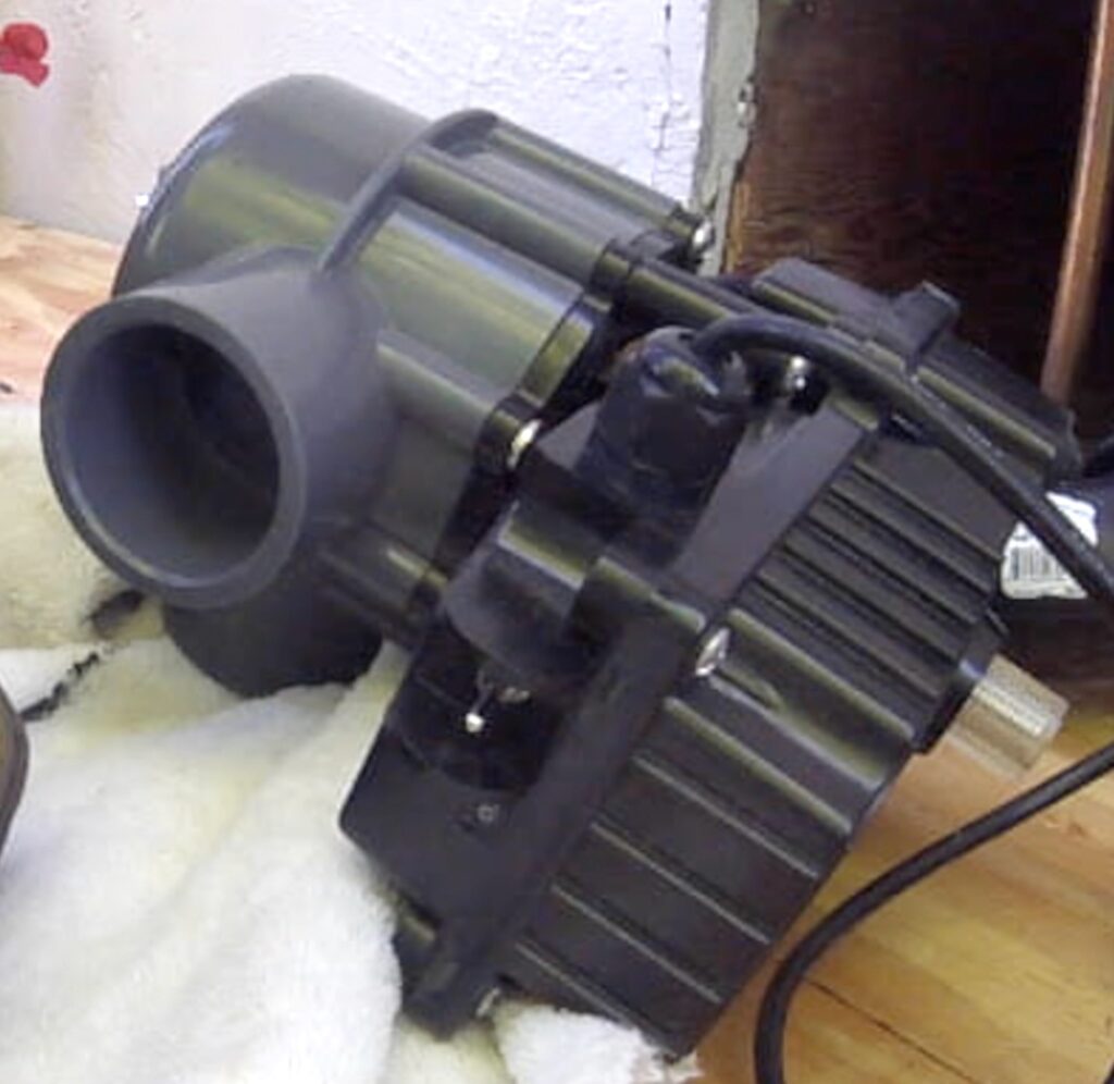
You always want to dry-fit your parts before gluing them in place. PVC and ABS glues work by dissolving the plastic. You’re welding the parts together – not with heat, as in metal, but with chemical action. Taking apart a join gone wrong doesn’t work.
As you see in the video, we installed our valve-actuator assembly upside down, with the valve inverted on top and actuator below it, because that’s what worked in the tight space with the pipes as they were.
Step 5: Gluing the Pipe Fittings
Glue the pipes a section at a time, as you see here. Deciding which pieces to glue at what point in time is a puzzle to solve. Don’t paint yourself into a corner that you can’t get out of.
To attach ABS pipes to the diverter valve, which is made out of PVC, use cement specific to that purpose: ABS-PVC cement.
We used removable flexible PVC pipe couplers on the section that included the sanitary tee, the piece that leads down to the sewer drain pipe and up to the vent, so we could easily remove it in the future if we ever need to service the valve or the actuator motor.
Step 6: How to Wire the Electric Actuator Switch
We mounted the operating switch for the actuator motor in a temporary plastic switch box, and plugged the power supply into an extension cord for the time being.
Power ordinarily comes from hooking the device into a pool or spa system, so it doesn’t come with a standard wall plug. You’ll need to get a 24v transformer. Check to see that the amp rating of the transformer is at least the same if not greater than the amp rating of the actuator or it won’t send sufficient power. Make sure the volts match.
For the control switch, you’ll need a single-pole double-throw (SPDT). If you get a simple on-off switch, then only one direction will connect an electric flow; the other will simply break it. A single-pole double-throw can send electricity both ways – one to turn the valve to send water to the sewer, the other to send water out to the landscape.
You don’t need to worry about turning it off, because once the valve reaches the end of its turn, the motor stops running automatically. Next time you want to switch valve directions, just turn the switch the other way. The motor turns the valve until the cams inside stop it.
If you’d like a more finished look, you can get a SPDT switch that looks like a standard indoor light switch. If you plan to mount it flush with the wall, you’ll need to run the wires through the wall and lead them into the space where the motor is.
The actuator motor has a cord coming from it made up of a red, a white, and a black wire. If there’s a handy little plug at the end, chop it off. It’s for plugging into the pool or spa system.
The power supply transformer has two wires. One attaches directly to the black wire from the actuator. Use a twist-on wire nut connector. Solder first if your local electrical code calls for it. Use a licensed electrician if you’re unsure.
The other wire from the power supply attaches to the middle terminal of the switch.
The red and white wires from the motor attach to the end terminals on the switch – one each.
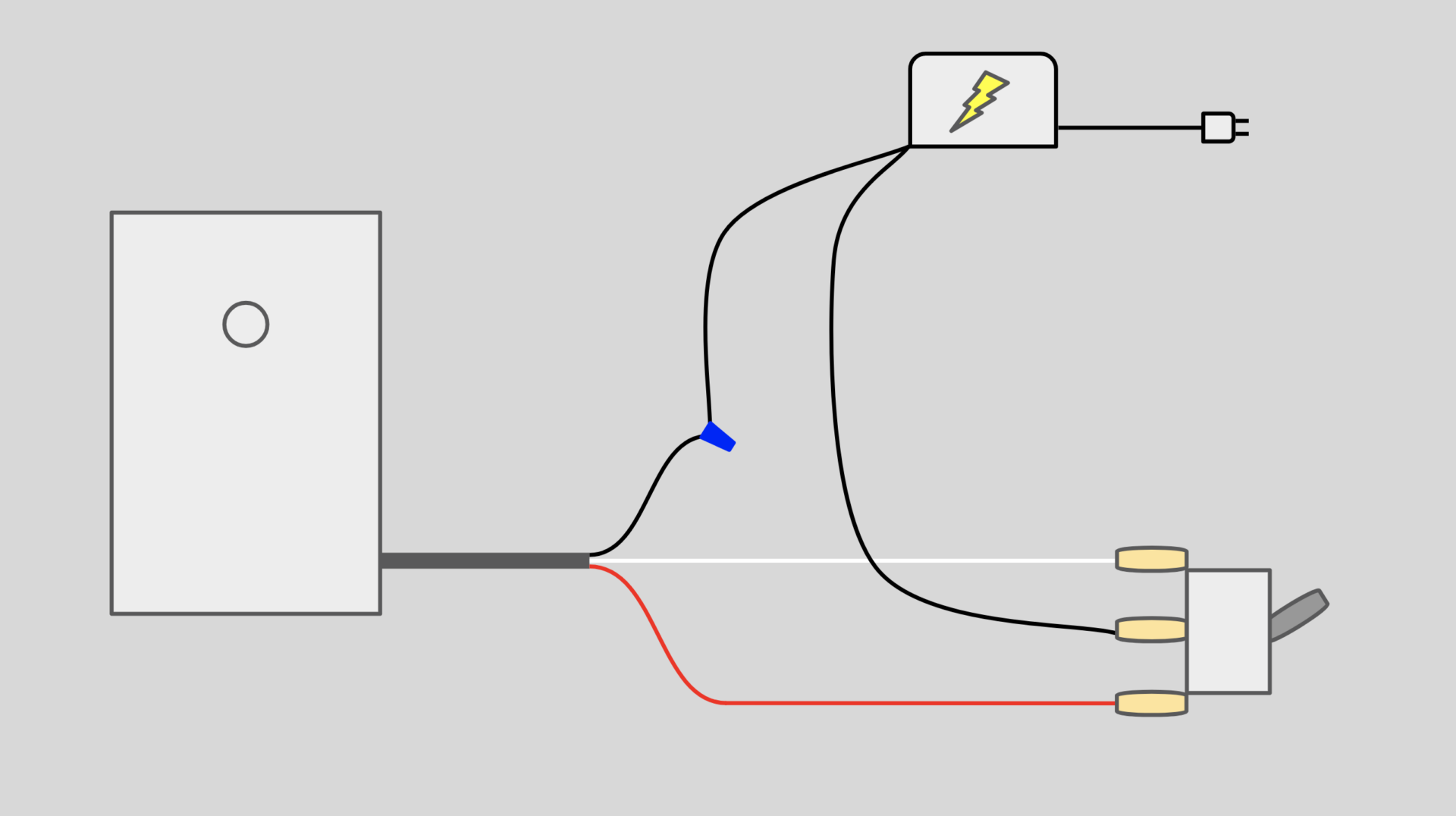
The electric flow logic should now be clear. The circuit goes like this:
Power flows from the power supply transformer into the center of the switch, then out to the motor through either the white wire if you turn the switch one way, or through the red wire if you turn it the other way.
When it flows through the white wire, the motor turns one way. When it flows through the red wire, it turns the other way.
Then the electricity completes the circuit by flowing back out of the motor through the black wire to the power supply.
Step 7: Gluing the Diverter Valve in Place
During dry-fitting we saw that the drain pipe held the incoming side of the valve assembly well enough in place, but the other side drooped. So we installed a hanger strap to hold it up.
Remember that when you glue pipes, you only have a few seconds to seat things right before they take hold. Be precise, and act fast.
Make sure the valve is turned toward the sewer at this point before you test for leaks. The graywater side isn’t hooked up yet, so you would definitely have a leak there!
When the city inspector looked over our work, he said we had to change one of the removable couplings and use the shielded kind in that spot instead. So we did.
Step 8: Framing an Access Doorway
This is where you weather-seal the hole you made. We smoothed up the opening, then relied heavily on caulking. A resource we found later that might be a better choice came from Matt Risinger’s video on working with tar paper.
If you have Tyvek house wrap instead, you might find guidance from Fine Homebuilding’s video on patching housewrap.
Note that we swapped out the shorter, sharper 90 for a long-sweep 90 for smooth flow.
Step 9: Building the Access Door
The thinking behind this door design, and the design for the framing as well, was to keep the access opening as large as possible. To get at the motor and valve, the sanitary tee section of the piping has to be removed, and the motor & valve together are already a pretty big object.
The framing boards encroached on the space, and a door jamb would have made it just that much smaller. A plug door with weather stripping around the outside edge was what we settled on.
Step 10: Mounting the Pipes to the Wall
Maintaining a proper slope of ¼ inch drop per foot of run means an angle of at least 1.15º. Because we were up high on the wall, we could afford to be generous and always gave more. If you have to run your pipes when you’re already below the house, you’ll need to be a lot closer to tolerance. You can get deep fast.
The way we sealed the pipe exit was to wrap it with rubber tape and twist it in tight. That spot will stand some regular inspection as time goes on.
Connecting the graywater side with another removable cuff allows us to pull the pipe out of the way in the future if we need to remove the valve and actuator. Because of where the sewer pipe was and where the target mulch basin was, the outflow pipe had to cross directly in front of the door.
Another removable cuff halfway along the wall provides another maintenance access point.
Note that we dry-fit the nails holding the J hooks in the wall just like we dry-fit the pipes before gluing. Make sure things line up right before making them permanent.
Step 11: Testing the System for Leaks
Having taken the temporary switch back apart for the intervening steps just to keep it out of the way, now that both sides of the output are connected, we wired it up once again. It was certainly a thrill to hear the water pouring down the pipes. And to find that our connections were secure.
Step 12: Finishing and Cleaning Up the Presentation
Painting the pipes serves two purposes: One, it looks nice. Two, it protects PVC from becoming brittle under ultraviolet rays. Always paint any PVC exposed to sunlight.
We also put a chunk of pink fiberglass insulation on the back of the door to replace the piece we pulled out when we first cut the wall.
The copper pipes there are the hot & cold water service pipes. You may have noticed in an earlier step that we put cylindrical foam insulation around them; the pink square is an added measure.
Step 13: Installing the Control Switch
Time to finalize the electricity. Power will come from the adjacent bedroom, and the control switch will be mounted discreetly in the bathroom closet rather than out in the room. Lengthen the wires of your circuit as needed to reach your placements.
Sending a string through the hidden no-man’s land behind the tub was a feat. Pulling it back through with the wires attached was easier.
A metal switch box with a wall-mount plate replaced our temporary plastic one. Threading the wires through metal channels on the outside of the wall kept them controlled and presentable.
Because we wanted to run the power cord through the smallest hole possible in the bedroom wall, we chose to cut the plug off the end, and attached a new one once it was through to the other side. Again be sure you’re following your local electrical code, and use a licensed electrician if you’re not sure.
Step 14: Final Test, Inspection – and Harvesting
A lot of people do this kind of work under the radar and don’t go to the trouble of getting a permit or getting a city inspector to sign off on the completion. That’s really too bad, because it’s so satisfying to get the official signature that says nobody will bother you about this again.
As you saw in Step 7, our city inspector directed us to change the kind of coupling we were using in one spot. He checked to make sure the graywater was going in below the surface and into a sufficiently large mulch basin. With that, he was satisfied.
Label your switch box clearly which way is the sewer and which is the garden.
It’s also wise to post an explanation about how the system works. Most jurisdictions require it. See our Legal page and related articles for more about that.
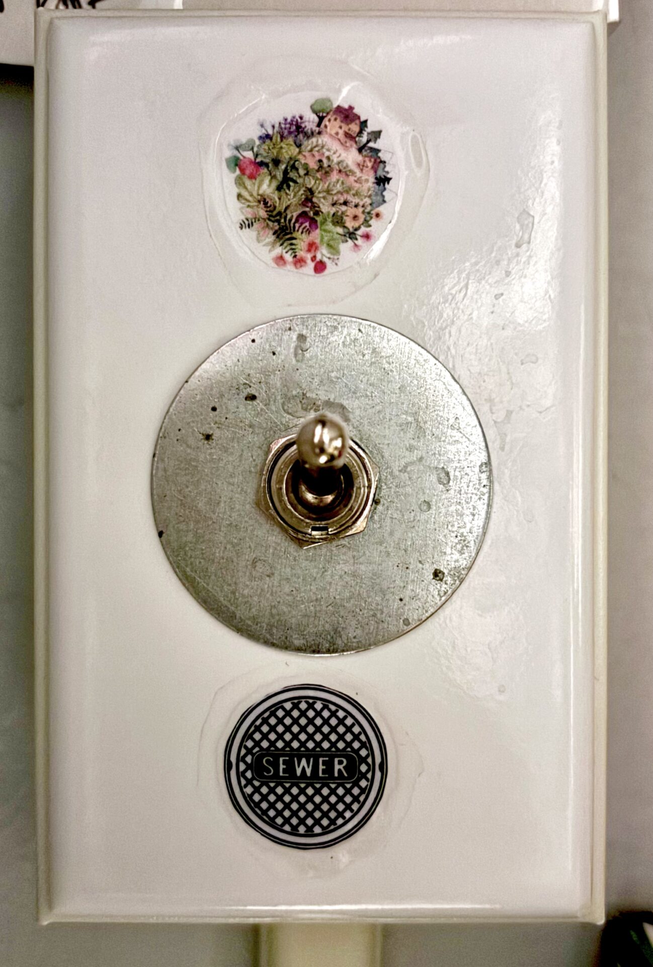
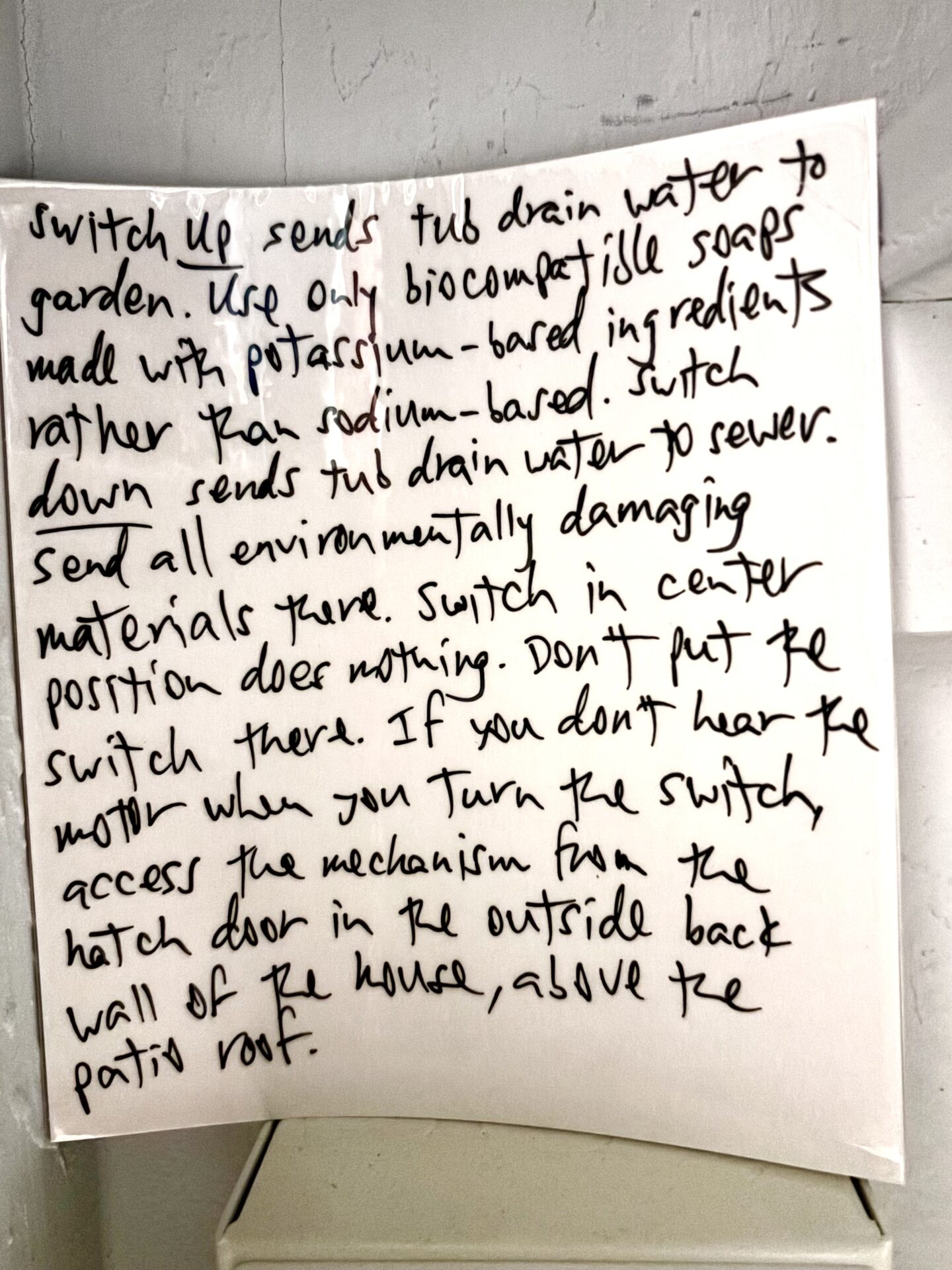
Label your graywater pipes with Reclaimed Water warning stickers. Check your local regulations for how far apart labels have to be applied.

Always use graywater-friendly soaps
Remember to use biocompatible soaps and hair products if you’re sending water out to the landscape. Review our Soaps page for guidance about the life you’ll be feeding, which feeds you in return.
